Before starting with the ZX97 I had to understand how the ZX video works. Therefore I took all information I could get and created this CPLD design. It replaces the original ZX81 ULA (user logic array) directly; so no changes in the computer are necessary.
It is written in the hardware description language EasyABEL, which was available as shareware. Today you might find free software packages for several computer operating systems (i. e. at Lattice Semiconductor) which contain ABEL compilers and much more. In EasyABEL I exported the compiled design as PALASM source, and then I used the package MACHXL (once made and given away for free by AMD) to generate the JEDEC file. This file can be read by most CPLD programmers to program the device.
For the CPLD I used the MACH210, just because I had some of these devices. It consists mainly of four GAL 22V16 structures. The design fits kentucky (if you don't know what this means, please consult "The Deeper Meaning of Liff" by the wonderful Douglas Adams), and I had to do some experiments with swapping pins to make it fit...
zx81vid.zip Archive with EasyABEL source and OrCAD schematics, 52KB.
MACH210.zip Datasheet of the CPLD, 299KB. This is copyrighted material of Lattice Semiconductor.
|
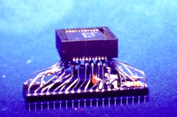
This thumbnail shows my prototype; click on the picture to get the big one, sized 48KB. As you can see, some few parts have to be added to get a real replacement for the ULA. Because it was just an experiment, I made no PCB layout, but maybe you like to? |
| Now the important thing, aside the CPLD data: the schematic. To get something you can work with, click on the thumbnail. You'll receive a PDF file of 32KB size. If you're able to read OrCAD files, fetch the archive and try your luck. |  |
To reproduce the built-in oscillator of the ULA, I had to look for a design that works with the ceramic resonator provided on the ZX's PCB. I have forgotten how this oscillator is named, but it works. To be sure that you can make it yourself, I tried several variations of values for the components, and it seems to be quite foolproof.
There's only one thing you have to find out yourself: the correct values of the resistors at the TV_TAPE pin. It depends on the circuitry you are using, maybe the original TV modulator, or a driver for a monitor. As long as you're not going below few hundreds Ohms at the series resistor R5, you can't harm the MACH210. My values are: 0 (zero) Ohms for R5, open (no resistor) for R6, and 4700 Ohms for R7.

Back to my home page.
Comments and such stuff go to: [email protected]